
This is a design for a 13.8 V power supply that can charge a sealed lead battery and simultaneously power equipment with a 13.8 V nominal supply voltage. Maximum current is 1.5 A and this can be delivered continuously, even when the output is short-circuited. Output current will be limited further when the regulators run too hot.
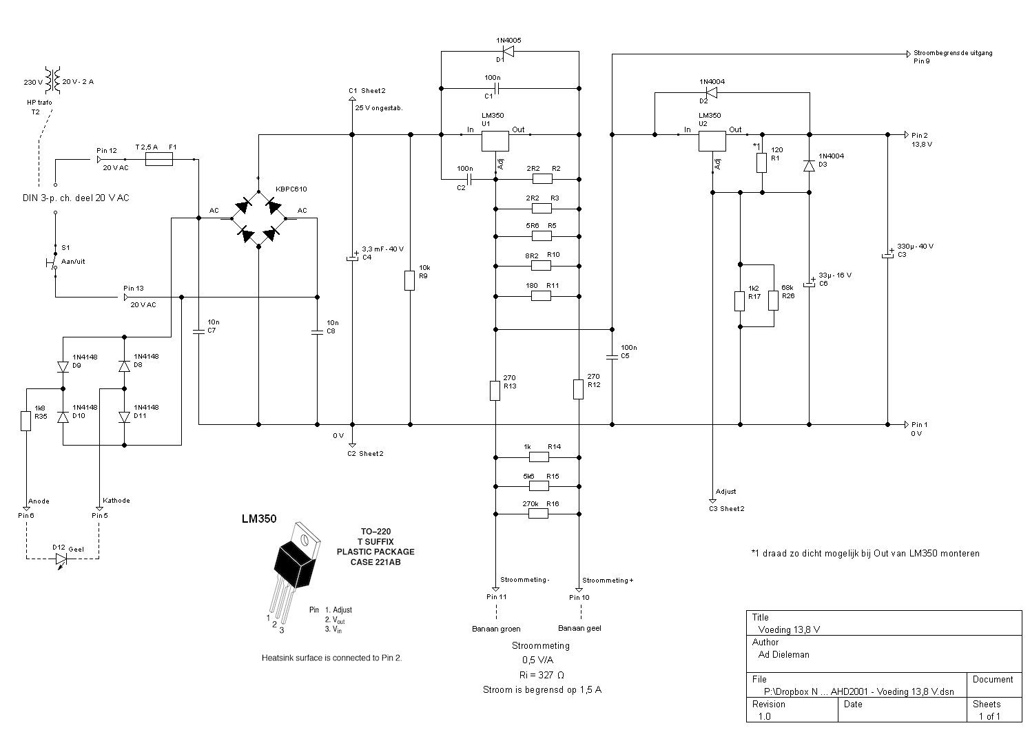
The main circuit consists of the mains transformer with a secundary 20 V – 2 A rating, rectifiers, buffer capacitor and regulators. The bridge rectifier must be suitable for at least 30 V and 2 A; I used one with a higher spec, always good to overdimension a bit. The first regulator U1 acts as a current limiter. The maximum current is determined by R2, R3, R5, R10 and R11; I combined resistors from my junk box to get to 1.5 A as close as possible. A single 0.82 Ω with a 5 W rating will get you close enough. Resistors R12…R16 constitute a circuit to measure the actual current and offer protection against accidental short circuiting of the measuring terminals; it is designed to yield 0.5 V/A with a 327 Ω internal resistance. Cooling of the regulators is important of course, get a cooling block of 2 K/W; if cooling is inadequate, the regulators will protect themselves from overheating by decreasing their output current.
The second regulator U2 functions as the voltage regulator for the 13.8 V output voltage. R1, R2 and R26 determine the output voltage; R1 should be 120 Ω, adjusting the output voltage should be done by varying R2 and R26. I don’t use potmeters or trimmers here because they can easily have bad contacts or be misadjusted, potentially damaging the equipment connected to the output. That’s why I adjusted the output by trying different resistor values. Nominally the value for R2 is 1205 Ω, but tolerances will almost surely necessitate to adjust this. For good output regulation it is absolutely essential that the connection between R1 to U2’s output pin is not shared with a wire that carries the output current; I have mounted a separate wire from R1 directly on the output pin.
The circuit for the power indicator LED looks a bit odd, but showing the presence of the AC voltage of the transformer is the only way to indicate that power is delivered to the output. When power is off and a battery is connected to the output, the whole DC part is powered by the battery due to the protection diodes around the regulators.

The second circuit provides temperature compensation for the output voltage. This whole circuit can be omitted if you don’t want or need this temperature compensation. Ideally a sealed lead battery should get a standby charging voltage of 13.8 V at 20º C, decreasing with 18 mV/K above that. This is done by using a small diode as a sensor at the outside of the cabinet because the temperature inside the cabinet can be much higher. The diode’s forward voltage has a temperature coefficient of -2.2. mV/K and this is amplified and converted to a current that draws from the adjust output of U2, decreasing the output voltage by around 18 mV/K.
Trimmer R32 should be set at 20º C such that the voltage over R31 is very low, say 50 mV. That way the temperature compensation starts to be effective above 20º C. Any diode or base-emitter of a transistor can be used as a sensor, just what is convenient. No harm is done when the diode’s leads are short-circuited or left unconnected. There are simpler ways to provide temperature compensation, but this circuit is safe and affects the output voltage in a predictable way, even when there’s a malfunction somewhere in this circuit.
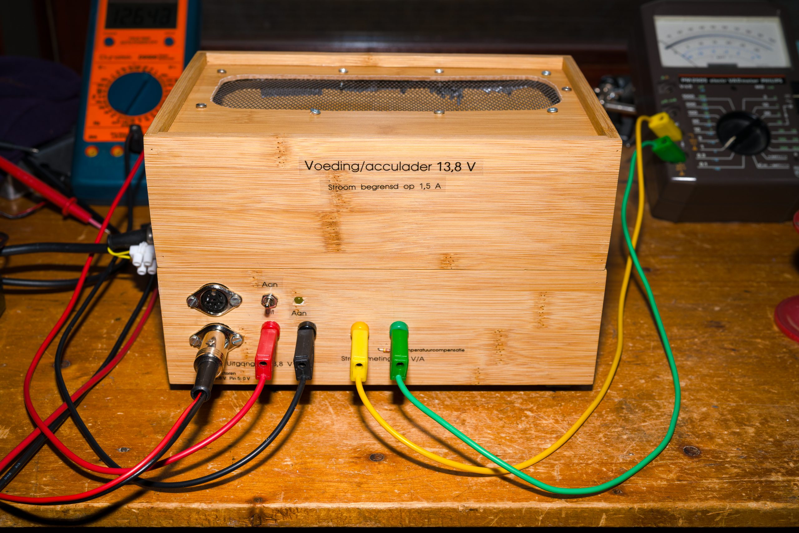
Usage is very simple: connect the equipment to the 13.8 V output and connect the battery in parallel. When the equipment draws less than 1.5 A, the battery is charged with the remaining current and the output voltage drops to the battery voltage. As most 13.8 V equipment is intended to be useable with a battery, the 12 V of an almost empty battery under charge will adequately power the equipment.