
A tuned loop is a very effective antenna for medium wave reception in an area with man-made noise. However, using such a loop in close proximity to a laptop computer with an SDR (software-defined radio) is not a good idea because the loop will pick up interference from the computer. Therefore I decided to build a loop antenna with remote tuning by varicaps (varistors if you prefer that term), picking up the idea from T.J. Nelson’s article. That way you can move the loop antenna to a spot further from the computer and possibly a spot with lower interference. Outside is best, so I’ll be aiming to build something that can withstand inclement weather (within reason!).
First the loop amplifier was built, intended to be used near the loop.
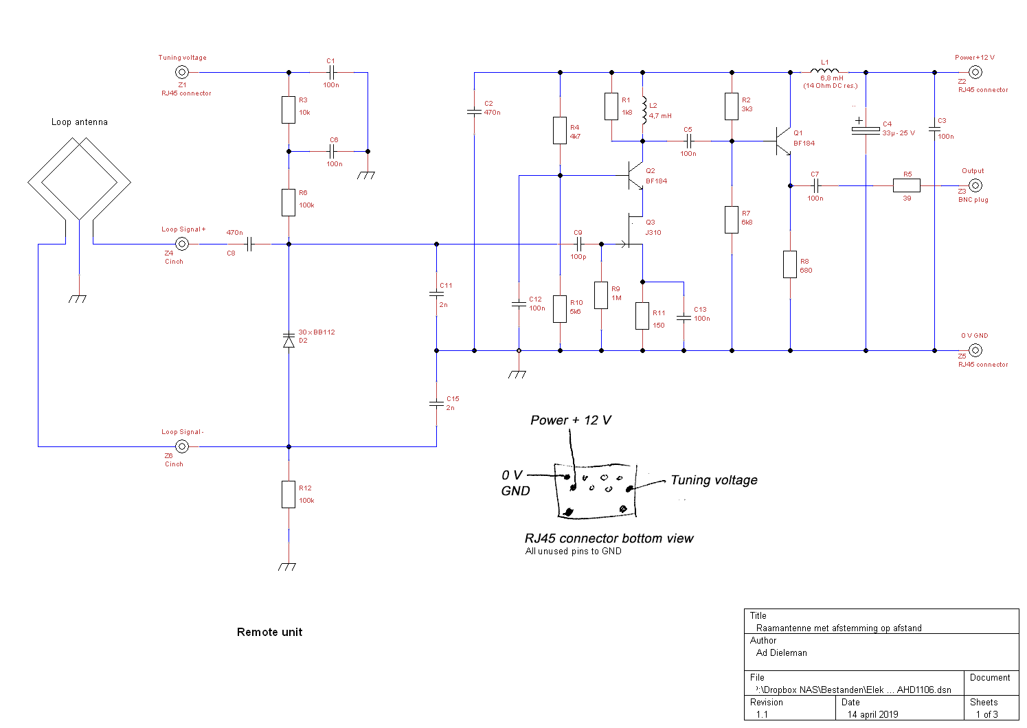
This is a fairly simple affair, consisting of an input stage with high input impedance to avoid loading the tuned-loop circuit, followed by a buffer stage to provide a 50 Ω output. The loop consists of two turns of unshielded wire, with a center tap connected to ground, resulting in a balanced loop; the input amplifier’s load is negligible. I’m not sure if C11 and C15 are really necessary but I just let them sit there for the time being. Earlier I added these capacitors in an effort to balance the loop, but that didn’t work very well, using the centre tap of the loop is much more effective in suppressing QRM.
The tuning range is 500-1800 kHz, spanning the entire medium-wave band. This is of course critically dependent on the loop dimensions; extra varicaps can be added if needed, and if the tuning frequency doesn’t come high enough, you can experiment with decreasing C11 and C15 or leaving them out altogether. Supply voltage can range between 10 and 15 V, current consumption is around 25 mA. The tuning voltage should be between 0 and 12 V (the maximum rating of the BB112 varicaps); there’s no point in raising the voltage above 9 V as the capacitance hardly decreases above that voltage. If you look at the BB112 datasheet, you’ll see that its capacitance is only shown for a minimum voltage of at least 0.3 V, depending on which manufacturer’s datasheet you use. I’ve found that applying a tuning voltage of 0 V isn’t a problem, reducing the number of varicaps required; this works because the loop has only two turns and is not very large, so the signal on the loop and the varicaps usually stays below 10 mV at my location (no large signals from nearby stations).
Next you need a control box to generate the tuning voltage and power for the loop amplifier. Here I’ve been profoundly lazy and built the simplest setup I could think of.
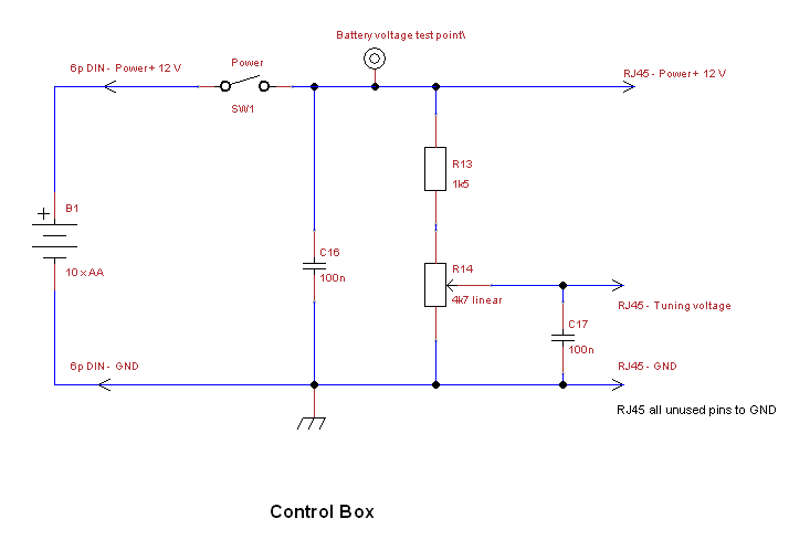
The power comes from 10 AA NiMH batteries and fully charged these will last for a few days. The tuning voltage is not stabilized; if that bothers you, it’s easy enough to add a 78L09 regulator for powering the tuning potmeter. Inspired by the design of the AOR LA400 antenna I use UTP cable for power and tuning voltage, the output signal is fed to the radio with RG-58 coax cable.
The loop consists of 2 turns of 40 x 33 cm.
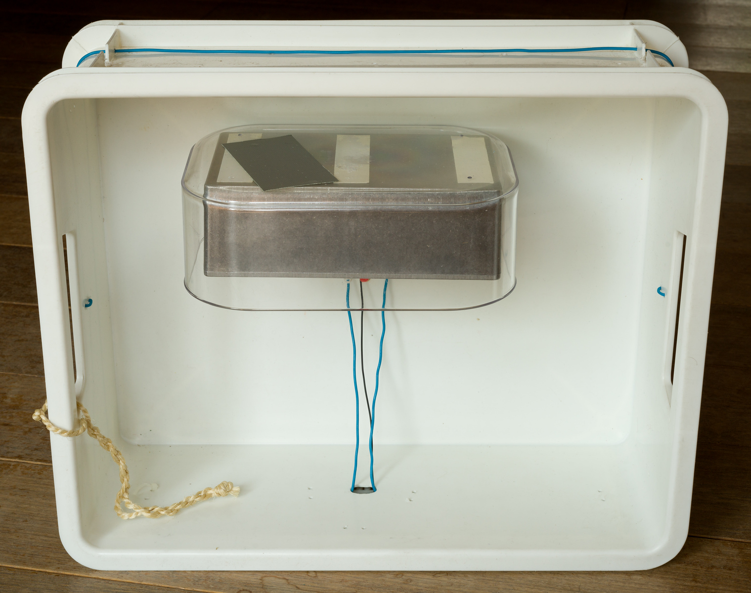
In the upside down view the connectors are visible. The plastic box is supposed to protect the bottom with the connectors from rain, but I’m afraid the plastic box will be too shallow for that, have to replace it by a deeper one. Alternatively, some plastic foil can be wrapped around. The black wire is the loop’s centre tab, the two wires left and right of it are the loop ends that carry the signal. And finally, the rope serves to hang the antenna off a fence in my garden.
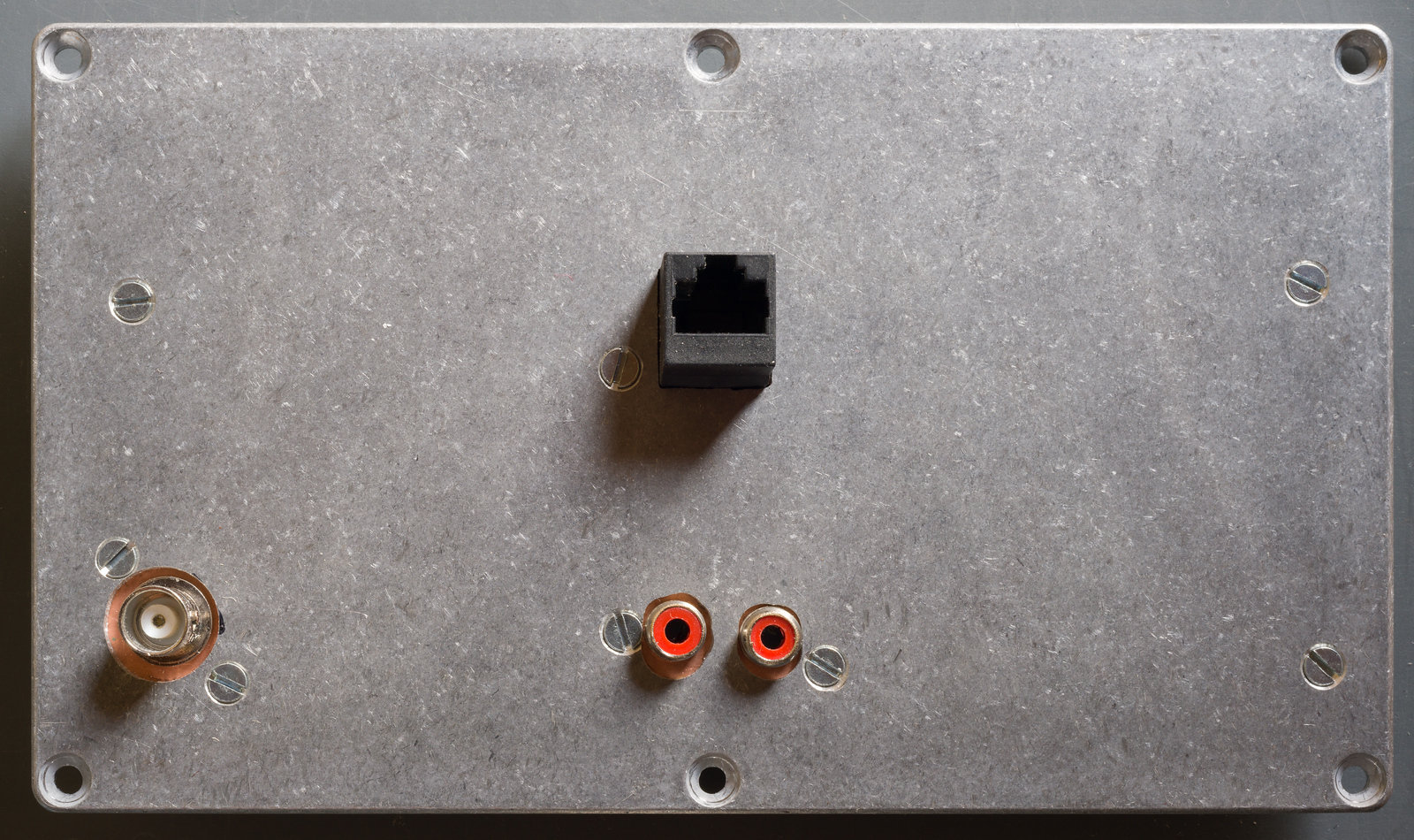
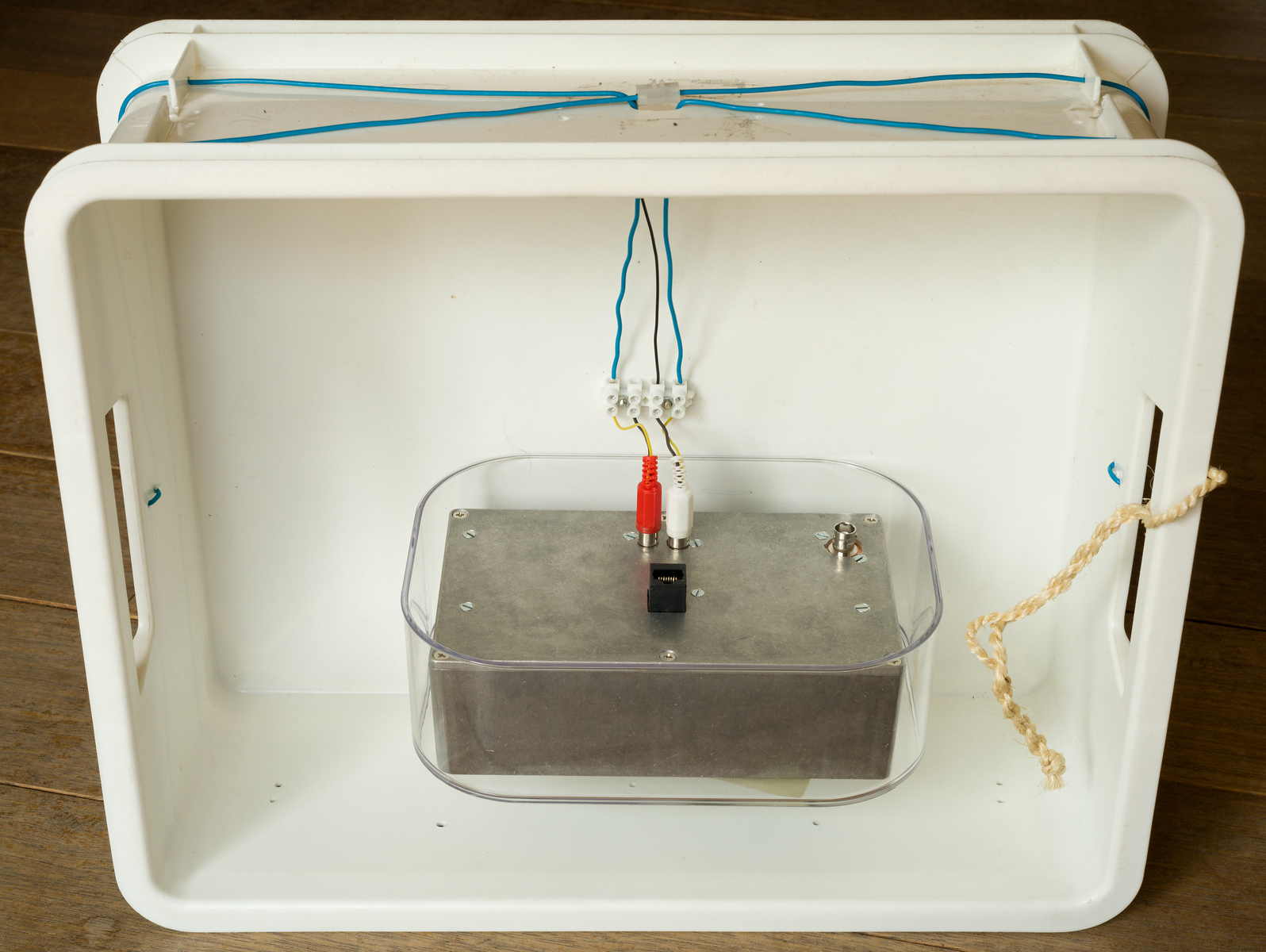
All connections of the amplifier box are placed at the bottom so that water does not run easily into the connectors. Lower left BNC connector is the 50 Ω output, the RJ-45 connector is for power and tuning voltage and the two Cinch ones are for the loop; the centre tap of the loop goes to one of the ground terminals of the Cinch connectors.
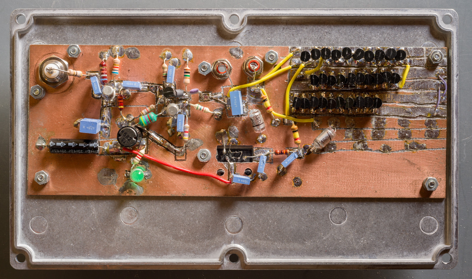
The loop amplifier circuit board is bolted to the bottom plate of the aluminium box and all connectors are directly mounted on the circuit board, avoiding wiring. Upper left shows the 30 varicaps that I ended up with, not as much as I had anticipated beforehand. Being able to get the circuit board out by just loosening 6 screws of the box is really convenient for modifications and experimenting.
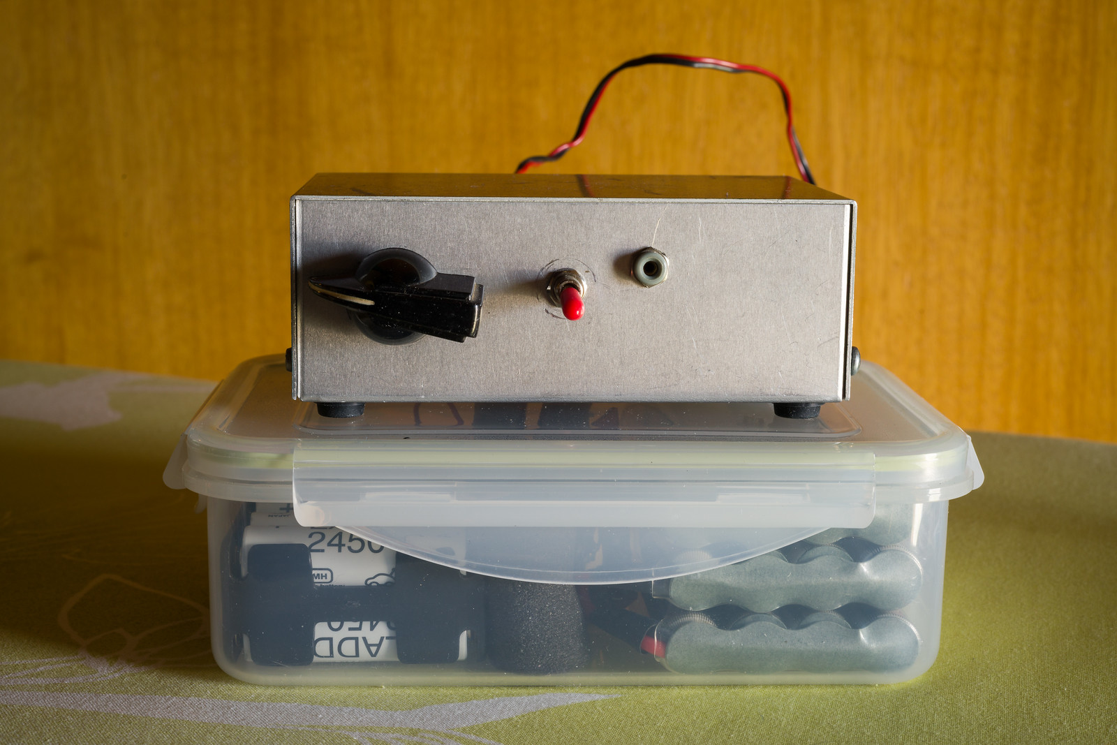
Tuning knob at the left, power switch in the middle and battery voltage test point at the right. The battery block contains 10 AA batteries for powering 12 V stuff and an additional 3 packs of 8 AA batteries each, because the battery block also serves to power my home-built radio.
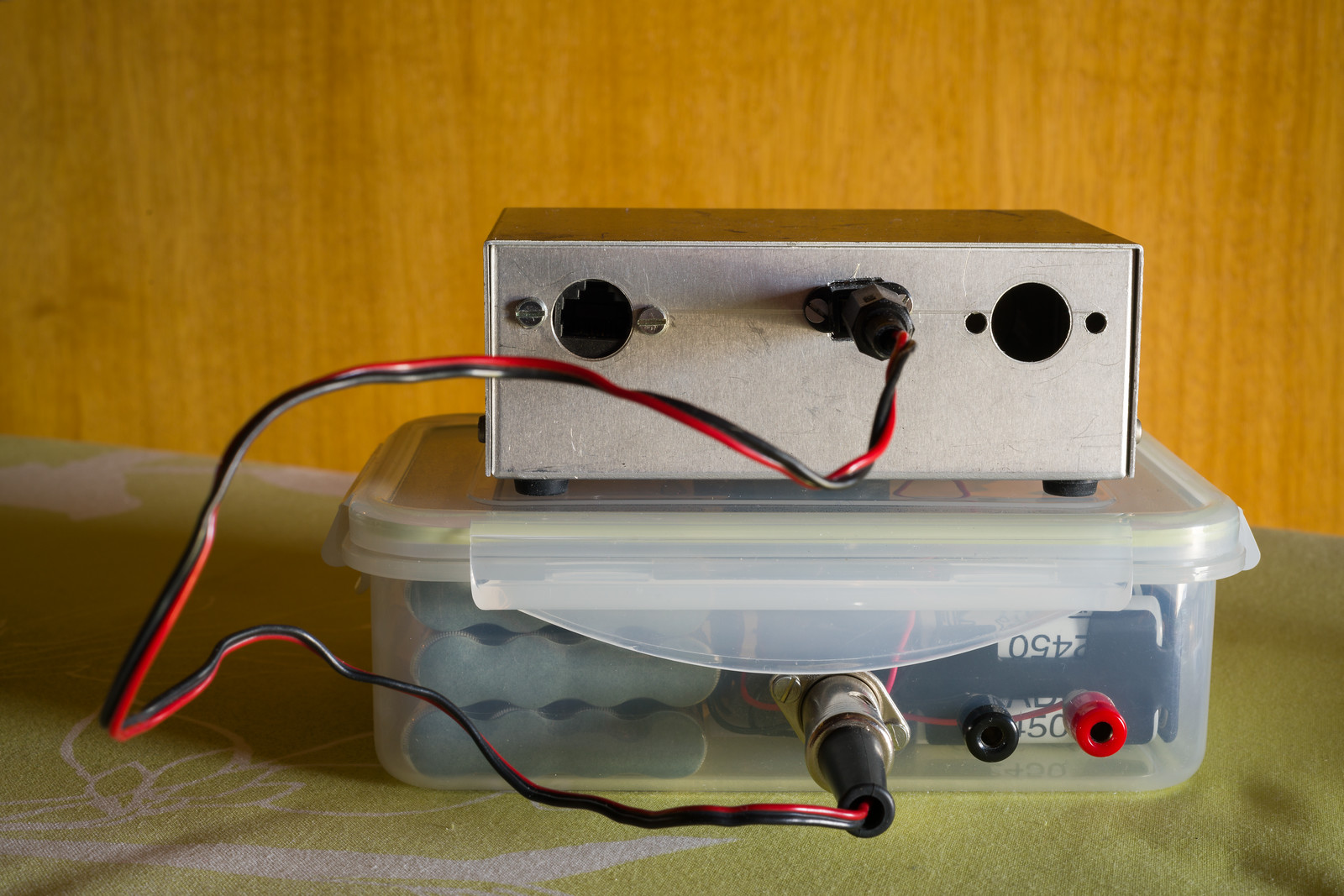
Left round hole has the RJ-45 connector for power and tuning, middle connector is 12 V power and the left hole is empty (the box was re-used from another project, which I even can’t remember). The battery block has a 6-pole DIN plug as power connector for both battery packs, this has become sort of my standard power interface. The black and red terminals are for charging the 24 AA battery pack, the 10 AA battery holder is simply taken out for charging.
And finally here’s a quick-and-dirty video I made of the antenna in operation, connected to my home-built receiver.
This looks very interesting and was thinking about building one myself. Do you make any changes or improvements? Thank you for posting this, as it is good inspiration.
Your homebuilt receiver intrigues me. Can you share any information on that?
You can find the schematic diagrams including block diagrams here. They’re in Dutch (made a long time ago). Hope you can find your way with this. I don’t have a description; please ask if you need clarification on specific items.
About the loop antenna, I didn’t use it very much because I moved on to doing FT8 on HF as a ham. The total setup is fairly sensitive to man-made noise, I haven’t managed to alleviate this problem.
Thanks for getting back to me. I found it interesting that your loop was very small and that you chose to use a lot of capacitance in the tuning part. I was thinking this would make the tuning very broadband. I appreciate all the information and this and the radio. I’m always looking for inspiration in what others have done.
Best regards,
-Rob